XDAQ Basics
Table of Contents
- What is resistance thermometer?
- What is VTTx and VTRx?
- What is Rx and Tx?
- SAC Overview
- Reference
- My other XDAQ related notes
- References
- Others
- Some materials to read
- Email: Checking OH Voltages and Temperatures
What is resistance thermometer?
There are several different types of thermometer, depening on the method using which it measures the temperature. For example a mercury placed in glass tube uses the rise/fall in height on the variation of temperature, a resistance thermometer uses change in reisistance of a meterial by the temperature variation.12
Resistance thermometers
As we know that the resistance of a meterial changes by changing the temperature. Thus, the resistance thermometer utilises this information for the resistance thermometer1. Resistance thermometers are also known as Resistance Temperature Detectors (RTDs), Platinum Resistance Thermometers (PRTs) or PT100 sensors. It is generally used to measure temperature varying from -200 to 500 $^0 C$. It is made from a lenght of fine wire either wrapped around a ceramic or glass core or deposited on a ceramic base2.
Generally, resistance thermometer uses platinum as it has high temperature coefficient of resistance as well as it has high melting point (1773 $^0C$). More basic details can be found at 3.
PT100 sensor temperature measurement
Reference:
- Email from Evaldas Juska forwarded by Brian Dorney
- Subject of email: “OH voltage and temperature monitoring”
There's not much information about the SCA chip temperature units, but
   some information can be found in the SCA manual page 52, which shows
   linear dependence of temperature from -37.5 deg C to 79 deg C
   corresponding to 790 counts for -37.5degC and going down to about 570
   counts for 79degC.

   For PT100 measurements, a more complex conversion is necessary to covert
   the ADC counts to temperature. The way it works is that the ADC supplies
   100uA current that goes through the PT100 sensor to ground, and the
   voltage drop over the sensor then corresponds to the temperature. The
   exact part number of the PT100 sensor we are using is P0K1.1206.2P.B,
   which has a resistance of 100 Ohms at 0 deg C, and changes by 0.385% per
   each degree C cumulatively (more info can be found here:
   http://www.farnell.com/datasheets/2207165.pdf?_ga=2.247382788.1064362929.1535377707-998824428.1535377707
   and here:
   https://www.intech.co.nz/products/temperature/typert/RTD-Pt100-Conversion.pdf).
   This means that at 0 deg C the voltage drop over the PT100 will be 100uA
   * 100 Ohms = 10mV, so the ADC will read 1.0V - 10mV = 0.99V, and if the
   temperature is 30 degC, the PT100 will have a resistance of 111.67 Ohms,
   and so the voltage drop will be 100uA * 111.67 Ohms = 11.167mV, so the
   ADC will read 1.0V - 11.167mV = 0.988833V.
References mentioned in above message:
- SMD platinum sensor: http://www.farnell.com/datasheets/2207165.pdf?_ga=2.247382788.1064362929.1535377707-998824428.1535377707
- Temperature Conversion Table for PT100 sensor used in GEM DAQ: https://www.intech.co.nz/products/temperature/typert/RTD-Pt100-Conversion.pdf
What is VTTx and VTRx?
The Versatile Link is a bi-directional digital optical data link operating at rates up to 4.8 Gbit/s and featuring radiation-resistant, magnetic field tolerant, low-power and low-mass front-end components. The system is proposed in multimode (MM) or singlemode (SM) versions operating at 850nm or 1310nm wavelength respectively. It has serial data interfaces and is protocol-agnostic, but is targeted to operate in tandem with the GigaBit Transceiver (GBT) serializer/deserializer chip at the front-end, and with a GBT core instantiated in an FPGA at the back-end. Test45
- Versatile Transceiver (VTRx)
- Versatile Twin Transmitter (VTTx)
- https://espace.cern.ch/project-versatile-link/public/Versatile%20Link%20Public%20Documents/Forms/AllItems.aspx
- https://espace.cern.ch/project-versatile-link/public/Versatile%20Link%20Public%20Documents/Publications/2017%20Versatile%20Transceiver%20production%20and%20quality%20assurance/Olantera_2017_J._Inst._12_C01097_VTRxProdStatus.pdf
- https://iopscience.iop.org/article/10.1088/1748-0221/8/02/C02053/meta
- https://iopscience.iop.org/article/10.1088/1748-0221/8/02/C02053/pdf
- https://espace.cern.ch/project-versatile-link/public/Versatile%20Link%20Public%20Documents/Application%20Note/Versatile%20Link%20Application%20Note%20v2.7.pdf
- https://indico.cern.ch/event/681247/contributions/2926593/attachments/1638413/2615045/Versatile_Link_and_GBT_Chipset_Production_ACES18.pdf
- https://edms.cern.ch/ui/file/1140665/1/VTRx_Spec_v2.2.pdf
What is Rx and Tx?
- What does “X” stand for in TX and RX?
- What is the difference between the RX rate and TX rate in MikroTik?
- What are the differences between TX and RX cables?
-
What is the TX and RX in the internet?
SAC Overview
- GBT-SCA flow diagram
- GBT chipset front-end system
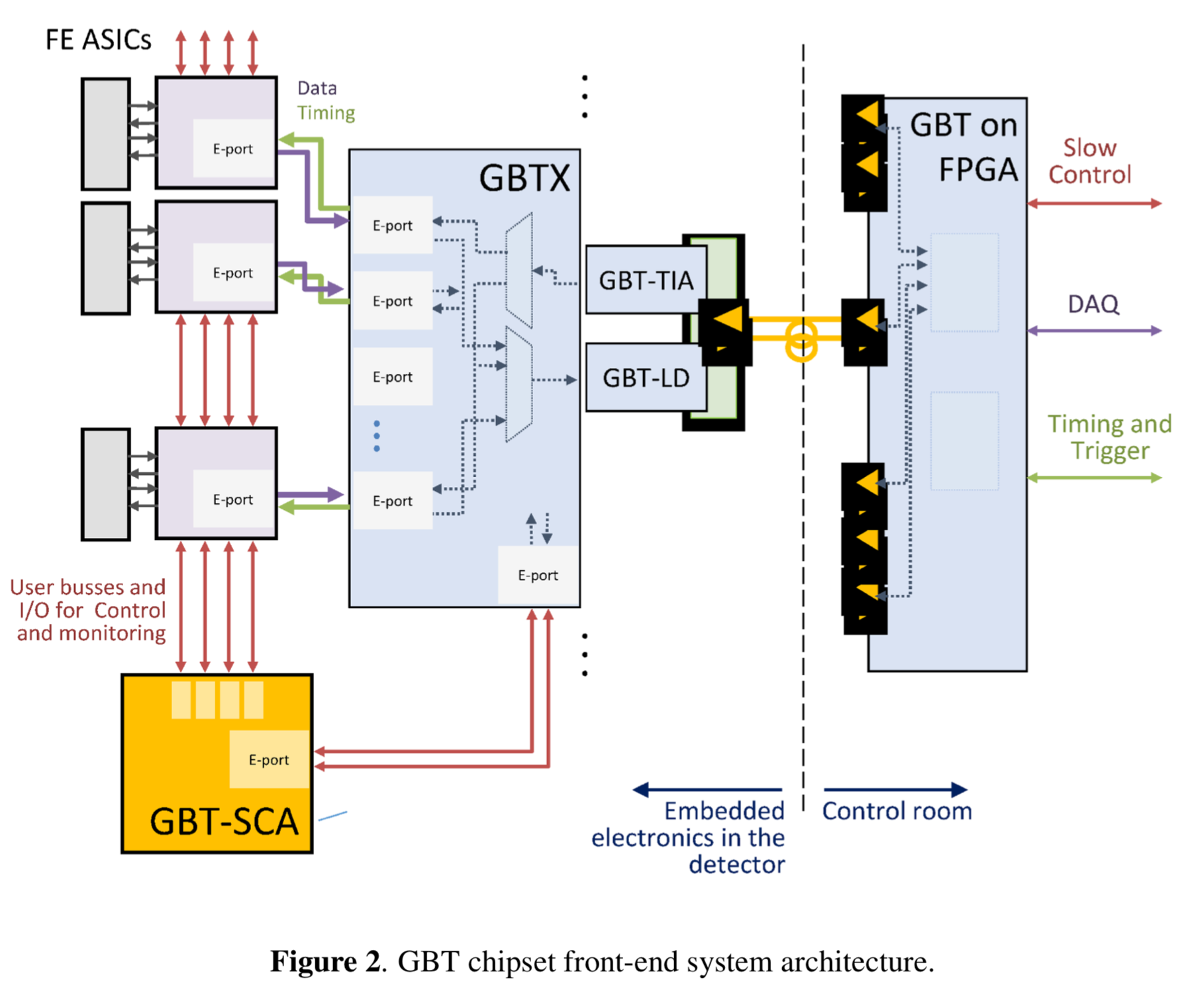
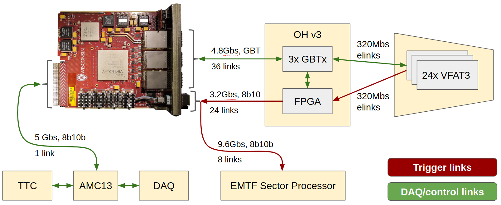
- GE1/1 backend connectivity
 Reference: https://twiki.cern.ch/twiki/bin/view/CMS/MuonGEMBackend#CMS_GEM_Backend_System
Some Useful Key Words
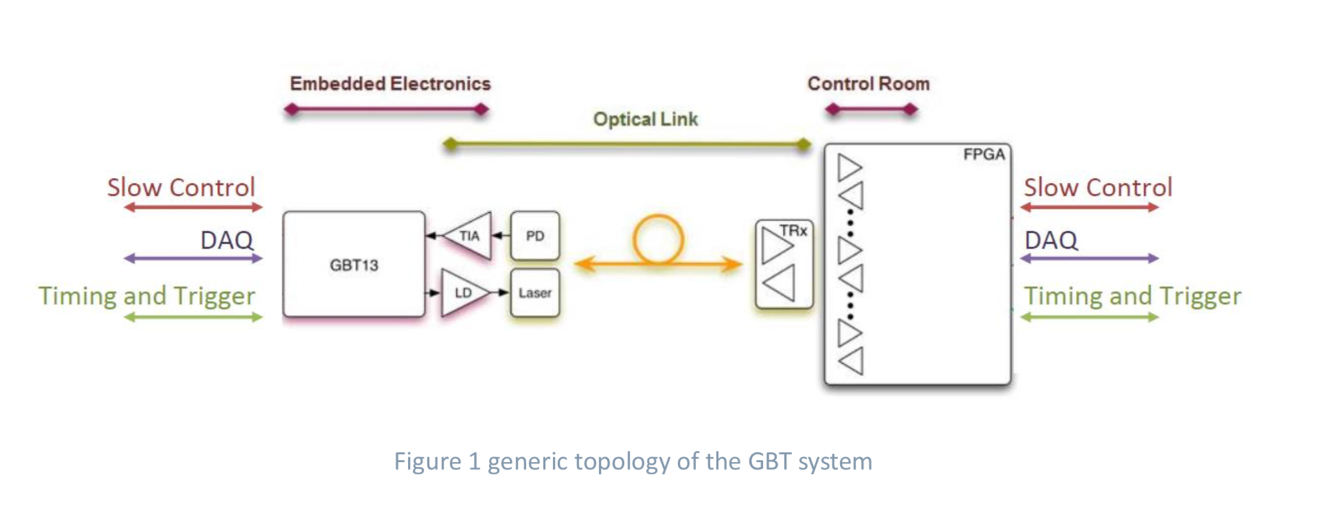
- GBT: Giga-Bit Transceiver Optical Link
- GBT was designed for transferring the readout data, timing and trigger signals along with the slow control and monitoring data, simultaneously, in a radiation hard environment.
- SEU:
- TID:
- SCA: Slow Control Adapter
- AMC13: It provides clock, timing and DAQ services to the uTCA carate either from the the TCDS system (at P5) or in local loopback mode (at a test stand).
- CTP7: Calorimeter Trigger Processor 7
- backend electronics of GE1/1.
- responsible for slow control (register read/write), tracking data readout, and event building
- For GE1/1 case it controls up to 12 optohybrids
- Optohybrids:
- uTCA:
- FPGA:
- LMDB: Ligntning in Memory Database
- LVDS: Low voltage differential signaling
- Protocol: A protocol is a set of rules through with the two computer communicates between them. Example of some protocol is PPP, TCP/IP, SLIP, HTTP, and FTP.
Reference
- GEM Electronics User Guide: Link
- LVDS user manual: Link
- ZYNQ System-on-Chip: link
- Virtex-7 FPGA: Link
- Understanding AXI protocol: Link
- AXI Reference guide: Link
- ARM AMBA: Link
- ARM AMBA (blog): Link
Official Reference
- GEM Electronics User Guide: Link
- CTP7 Module (GitHub): Link
- GEM backend system: Twiki Link
- GBTX Manuals (CERN): Link
- GE1/1 Electronics presentation: Link
- Using XDAQ in Application Scenarios of the CMS Experiment: link
My other XDAQ related notes
References
- Development of the DAQ System of Triple-GEM Detectors for the CMS Muon Spectrometer Upgrade at LHC, PhD Thesis, Lenzi, Thomas and De Lentdecker, Gilles, CERN-THESIS-2016-215
- http://inspirehep.net/record/1632245/files/fulltext.pdf
- https://indico.cern.ch/event/468486/contributions/1144322/attachments/1240303/1823447/PAspell_ACES2016.pdf
- https://indico.cern.ch/event/608587/contributions/2614200/attachments/1522303/2378769/GE11-TWEPP17-v2.0.pdf
- https://iopscience.iop.org/article/10.1088/1748-0221/12/02/P02003/pdf
Others
- GEM Cosmic Stand: https://twiki.cern.ch/twiki/bin/viewauth/CMS/GEM904CosmicStand
- SCA reser procedure: https://twiki.cern.ch/twiki/bin/view/CMS/GEMDOCDoc
- Elog of
QC7-electronic-test: https://cmsonline.cern.ch - Explanation of scurve: https://indico.cern.ch/event/780422/contributions/3252280/attachments/1771243/2879820/BDorney_GEMDAQMtg_20181213_SCurve.pdf
Some materials to read
- CTP7 module github readme: https://github.com/cms-gem-daq-project/ctp7_modules/blob/develop/README.md
- GEM electronics user guide: https://github.com/cms-gem-daq-project/sw_utils/blob/develop/v3ElectronicsUserGuide.md
- GBT SCA user manual: https://espace.cern.ch/GBT-Project/GBT-SCA/Manuals/GBT-SCA-UserManual.pdf
- FW docs:
- CTP7 v3 Address Table : https://www.dropbox.com/s/r1vic58oh12t9i3/table_ctp7.pdf?dl=0
- Optohybrid v3 Address Table : https://www.dropbox.com/s/qb3i2omxjba0ug3/table_oh.pdf?dl=0
Email: Checking OH Voltages and Temperatures
Reference: - Email from Evaldas Juska forwarded by Brian Dorney - Subject of email: “OH voltage and temperature monitoring”
   OHs have two separate paths to read various voltages and temperatures:
      * Xilinx FPGA SysMon can be accessed by JTAG and provides FPGA core
   temperature, Vccint (core voltage, should be 1V), and Vccaux (I/O
   voltage, should be 2.5V). These readings can be accessed by sca.py
   sysmon function. Although generally accessing the JTAG port is not
   recommended during stable operation since it has been shown to cause
   strange problems in CSC, besides it's doubtful how much useful info one
   could get from the sysmon voltage readings since sysmon itself would
   likely stop functioning if these voltages are out of range (especially
   the core voltage)
      * SCA ADC is monitoring several voltages on the OH board, as well as
   PT100 temperature sensors. This is the recommended method to monitor the
   OH voltages and temperatures, and the procedure of how to do it is
   outlined below.

   CTP7 is instructing the SCA to cycle through ADC channels and readout
   measurements any time the SCA is idle. This can be disabled in order to
   not interfere with SCA command heavy operations like accessing the JTAG
   chain e.g. for programming the OH FPGA, because even though the ADC
   measurements are done in idle periods, they do take a lot of time to
   complete and can delay new SCA command requests and even result in a
   timeout for these new incoming commands. SCA ADC monitoring registers
   are located under GEM_AMC.SLOW_CONTROL.SCA.ADC_MONITORING. Monitoring
   can be enabled/disabled by MONITORING_OFF register, which is a bitmask
   that defines for which OHs this monitoring should be off/paused
   (monitoring is stopped by sca.py tool for most SCA operations). Once the
   monitoring is enabled, these readonly registers will be updating every
   ~200us (one channel at a time):
      * AVCCN       (1.0V MGT power, used in 8b10b links e.g. trigger links)
      * AVTTN       (1.2V MGT power, used in 8b10b links e.g. trigger links)
      * 1V0_INT     (1.0V FPGA core power)
      * 1V8F        (1.8V PROM power)
      * 1V5         (1.5V power for GBTX and SCA)
      * 2V5_IO      (2.5V FPGA I/O power)
      * 3V0         (3.3V supply used as input to 1.5V, 2.5V, and 1.8V
   regulators, also used for CCB interface, and JTAG)
      * 1V8         (1.8V supply used as input to AVCCN 1.0V, AVTTN 1.2V,
   and 1.0V FPGA core regulators)
      * VTRX_RSSI2  (Signal strength of VTRX2, although this is not useful
   due to a hardware design flaw)
      * VTRX_RSSI1  (Signal strength of VTRX1, although this is not useful
   due to a hardware design flaw)
      * SCA_TEMP    (SCA chip temperature)
      * BOARD_TEMP1 (voltage drop over PT100 temperature sensor in position
   R720)
      * BOARD_TEMP2 (voltage drop over PT100 temperature sensor in position
   R721)
      * BOARD_TEMP3 (voltage drop over PT100 temperature sensor in position
   R722)
      * BOARD_TEMP4 (voltage drop over PT100 temperature sensor in position
   R723)
      * BOARD_TEMP5 (voltage drop over PT100 temperature sensor in position
   R724)
      * BOARD_TEMP6 (voltage drop over PT100 temperature sensor in position
   R725)
      * BOARD_TEMP7 (voltage drop over PT100 temperature sensor in position
   R726)
      * BOARD_TEMP8 (voltage drop over PT100 temperature sensor in position
   R727)
      * BOARD_TEMP9 (voltage drop over PT100 temperature sensor in position
   R728)

   Note that all voltages are divided by 3 on the OH board by a voltage
   divider (temperature sensor voltage is not divided).

   All values are in units of ADC counts, and this is a 12bit ADC with a
   range of 0.0 - 1.0V, so each count is 1V / 4095 = 0.244mV.

   There's not much information about the SCA chip temperature units, but
   some information can be found in the SCA manual page 52, which shows
   linear dependence of temperature from -37.5 deg C to 79 deg C
   corresponding to 790 counts for -37.5degC and going down to about 570
   counts for 79degC.

   For PT100 measurements, a more complex conversion is necessary to covert
   the ADC counts to temperature. The way it works is that the ADC supplies
   100uA current that goes through the PT100 sensor to ground, and the
   voltage drop over the sensor then corresponds to the temperature. The
   exact part number of the PT100 sensor we are using is P0K1.1206.2P.B,
   which has a resistance of 100 Ohms at 0 deg C, and changes by 0.385% per
   each degree C cumulatively (more info can be found here:
   http://www.farnell.com/datasheets/2207165.pdf?_ga=2.247382788.1064362929.1535377707-998824428.1535377707
   and here:
   https://www.intech.co.nz/products/temperature/typert/RTD-Pt100-Conversion.pdf).
   This means that at 0 deg C the voltage drop over the PT100 will be 100uA
   * 100 Ohms = 10mV, so the ADC will read 1.0V - 10mV = 0.99V, and if the
   temperature is 30 degC, the PT100 will have a resistance of 111.67 Ohms,
   and so the voltage drop will be 100uA * 111.67 Ohms = 11.167mV, so the
   ADC will read 1.0V - 11.167mV = 0.988833V.
-
A-level Physics, Muncaster R., ISBN:9780748715848 ↩ ↩2
-
https://www.peaksensors.co.uk/what-is/resistance-thermometer/ ↩ ↩2
-
https://blog.beamex.com/pt100-temperature-sensor ↩
-
https://edms.cern.ch/ui/#!master/navigator/document?D:1275981158:1275981158:subDocs ↩
-
https://indico.cern.ch/event/681247/contributions/2926593/attachments/1638413/2615045/Versatile_Link_and_GBT_Chipset_Production_ACES18.pdf ↩
Enjoy Reading This Article?
Here are some more articles you might like to read next: